


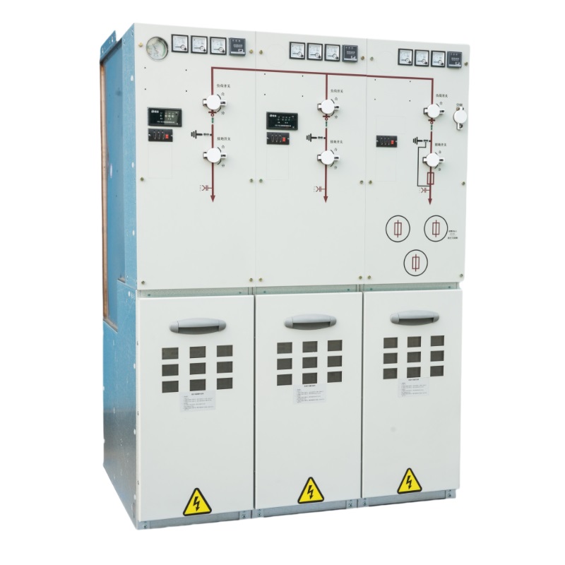
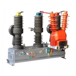
SSU-12 series SF6 gas insulated Ring Main Unit


Our fully insulated intelligent ring network cabinets cover SF6 gas insulated series, solid insulated series and environmental protection gas insulated series. After research and development, design and manufacture, we are fully equipped with the production capacity of standardized ring network cabinets and have obtained relevant third-party test reports.
At present, they are widely used in distribution systems with high power supply reliability requirements, such as urban commercial centers, industrial concentrated areas, airports, electrified railroads and high-speed highways.


Altitude
≤4000m (Please specify when the equipment operates at an altitude above 1000m so that the inflation pressure and the strength of the air chamber can be adjusted during manufacture).

Ambient temperature
Maximum temperature: +50°C;
Minimum temperature: -40°C;
The average temperature in 24h does not exceed 35℃.

Ambient Humidity
24h relative humidity not exceeding 95% on average;
The monthly relative humidity does not exceed 90% on average.

Application Environment
Suitable for highland, coastal, alpine and high filth areas; Seismic intensity: 9 degrees.
| No. | Standard No. | standard name |
|
1 |
GB/T 3906-2020 | 3.6 kV~40. 5kV AC metal-enclosed switchgear and control equipment |
|
2 |
GB/T 11022-2011 | Common technical requirements for high voltage switchgear and control gear standards |
|
3 |
GB/T 3804-2017 | 3.6 kV~40. 5kV high voltage AC load switch |
|
4 |
GB/T 1984-2014 | High voltage AC circuit breaker |
|
5 |
GB/T 1985-2014 | High Voltage AC Disconnects and Earthing Switches |
|
6 |
GB 3309-1989 | Mechanical test of high voltage switchgear at room temperature |
|
7 |
GB/T 13540-2009 | Seismic Requirements for High Voltage Switchgear and Controlgear |
|
8 |
GB/T 13384-2008 | General technical requirements for packaging of mechanical and electrical products |
|
9 |
GB/T 13385-2008 | Packaging Drawing Requirements |
|
10 |
GB/T 191-2008 | Packaging, storage and transportation icons |
|
11 |
GB/T 311. 1-2012 | Insulation coordination - Part 1 Definitions, principles and rules |

Compact

High Flood

Small Volume

LIght Weight

Maintenance Free

Fully Insulated

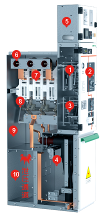
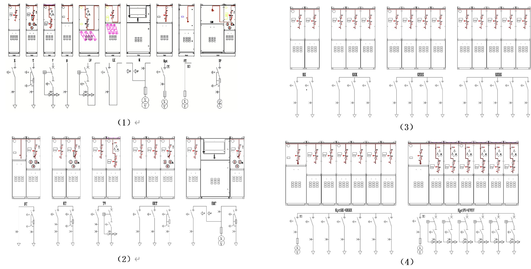
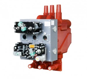
Major component arrangement
① Main switch mechanism ② Operation Panel ③ isolation agency
④ Cable Warehouse ⑤ Secondary control box ⑥ Busbar connection sleeves
⑦ Arc extinguishing device ⑧ Isolation switch ⑨ Fully enclosed box
⑩ Internal pressure relief device of the box
※Cable bin
1.The cable compartment can only be opened when the feeder has been isolated or grounded.
2.The casing pipe shall comply with DIN EN 50181 standard and shall be connected with M16 bolts. The arrester can be connected behind the T-shaped cable head.
3.The integrated CT is located at the casing side, which is convenient for cable installation and is not affected by external forces.
4.The height from the casing pipe installation place to the ground shall be more than 650mm.
※Pressure relief channel
In case of internal arcing fault, the special pressure relief device installed at the lower part of the body will automatically start.

Standard configuration and characteristics
• 630 A internal bus
• Earthing switch
• Two position single spring operating mechanism
• Grounding switch position indication
• Outgoing bushing horizontally arranged at the front, 400 series bolt bushing of 630A
• Capacitive voltage indicator indicating bushing electrification
• For all switch functions, there is a convenient padlock device on the panel
• SF6 gas pressure gauge (only one in each SF6 gas tank)
• Grounding busbar
• Interlocking between grounding switch and front panel of cable room
Optional Configurations and Features
• Reserved external bus extension
• External busbars
• Short circuit and ground fault indicator
• Measuring ring current transformer and ammeter
• Metering ring current transformer and watt hour meter
• MWD lightning arrester or double cable head can be installed at the cable inlet bushing
• Key interlock
• Incoming live grounding lockout (grounding switch lockout when bushing is live)

※Three position load switch
Three position design is adopted for closing, opening and grounding of load switch, which is safe and reliable. Rotating blade +arc extinguishing grid have better insulation and breaking performance.

※Load switch mechanism
Single spring double operating shafts design, built-in reliable closing, opening, grounding limit interlock device, ensure that closing and opening have no obvious overshoot. The mechanical life of the product is more than 10000 times, and the electrical components are pre designed, which can be installed and maintained at any time.
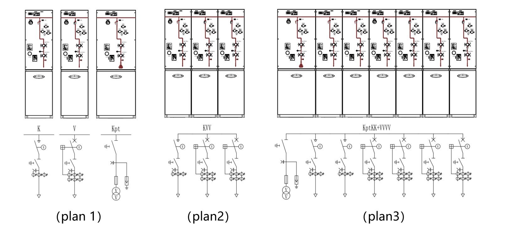
Main component arrangement
1. Load switches mechanism 2. Operation Panel
3. Cable Warehouse 4. Secondary control box
5. Busbar connection sleeves 6. Three-position load switch
7. Fully enclosed box 8. Internal pressure relief device of the box
※Cable bin
1.The cable compartment can only be opened when the feeder has been isolated or grounded.
2.The casing pipe shall comply with DIN EN 50181 standard and shall be connected with M16 bolts. The arrester can be connected behind the T-shaped cable head.
3.The integrated CT is located at the casing side, which is convenient for cable installation and is not affected by external forces.
4.The height from the casing installation place to the ground shall be more than 650mm.
※Pressure relief channel
In case of internal arcing fault, the special pressure relief device installed at the lower part of the body will automatically start.

Standard configuration and characteristics
• 630A internal busbar
• Three position load switch, the fuse head end and the fuse end grounding switch are mechanically linked
• Three position double spring operating mechanism, with two independent load switch and grounding switch operating shafts
• Position indication of load switch and grounding switch
• Fuse cartridge
• Fuse placed horizontally
• Fuse trip indication
• Outgoing bushing horizontally arranged at the front, 200A 200 series plug-in casing pipe
• Capacitive voltage indicator indicating casing pipe electrification
• For all switch functions, there is a convenient padlock device on the panel
• SF6 gas pressure gauge (only one in each SF6 gas tank)
• Grounding busbar
• Fuse parameters for transformer protection
-12 kV, 125 A maximum fuse
-24 kV, maximum 63 A fuse
• Interlocking between grounding switch and front panel of cable room
Optional Configurations and Features
• Reserved external bus extension
• External busbars
• Motors for vacuum circuit breaker operation DC 24V/48V, DC 110V/220V
• Shunt trip coil DC 24V/48V, DC 110V/220V
• Measuring ring current transformer and ammeter
• Metering ring current transformer and watt hour meter
• Key interlock (e.g. Ronis lock)
• Incoming live grounding lockout (grounding switch lockout when casing pipe is live)
※Three position load switch
Three position design is adopted for closing, opening and grounding of load switch, which is safe and reliable. Rotating blade +arc extinguishing grid have better insulation and breaking performance.
※Combination apparatus mechanism
The combined electrical apparatus mechanism with fast opening (tripping) function is equipped with reliable closing, opening and grounding limit interlocking devices to ensure that there is no obvious overshoot during closing and opening. The mechanical life of the product is more than 10000 times, and the electrical components are pre designed, which can be installed and maintained at any time.

※Lower grounding switch
When the fuse is blown, the lower grounding can effectively eliminate the residual charge on the transformer side, ensuring personal safety when replacing the fuse.

※Fuse cartridge
The three-phase fuse cartridges are arranged in an inverted triangular structure, and are completely sealed with the air box surface with a sealing ring, which can ensure that they are not affected by the external environment. As long as the striker is triggered after one phase fuse is fused, the load switch will be opened by quick tripping, so as to ensure that the transformer will not have the risk of phase loss operation.
Arrangement of main components
① Main switching mechanism ② Operation panel
③ Isolation mechanism ④ Cable compartment
⑤ Secondary control box ⑥ Busbar connection sleeve
⑦ Arc extinguishing device ⑧ disconnecting switch
⑨ fully enclosed box ⑩ box internal pressure relief device
※Cable bin
The cable compartment can only be opened when the feeder has been isolated or grounded.
The casing pipe complies with DIN EN 50181 standard, and is connected with M16 bolts. The arrester can be connected behind the T-shaped cable head.
The integrated CT is located at the casing side, which is convenient for cable installation and is not affected by external forces.
The height from the casing installation position to the ground is more than 650mm.
Standard configuration and characteristics
• 630A internal busbar
• Two position double spring operating mechanism for vacuum circuit breaker
• Three position isolating/grounding switch at the lower part of vacuum circuit breaker
• Three position isolating/grounding switch single spring operating mechanism
• Mechanical interlock of vacuum circuit breaker and three position switch
• Position indication of vacuum circuit breaker and three position switch
• Self powered electronic protection relay REJ603 (with protection CT)
• Trip coil (for relay action)
• Outgoing bushing horizontally arranged at the front, 400 series bolt casing pipe of 630A
• Capacitive voltage indicator indicating casing pipe electrification
• For all switch functions, there is a convenient padlock device on the panel
Grounding busbar
• Interlocking between grounding switch and front panel of cable room
Optional Configurations and Features
• Reserved external busbar extension
• External busbars
• Motors for vacuum circuit breaker operation DC 24V/48V, DC 110V/220V
• Shunt trip coil DC 24V/48V, DC 110V/220V
• Measuring ring current transformer and ammeter
• Metering ring current transformer and watt hour meter
• Key interlock (e.g. Ronis lock)
• Incoming live grounding lockout (grounding switch lockout when casing pipe is live)

※Circuit breaker mechanism
The precision transmission mechanism with reclosing function is connected by V-shaped key. The shaft support of the transmission system adopts a large number of rolling bearing design schemes, which are flexible in rotation and high in transmission efficiency, so as to ensure the mechanical life of the product more than 10000 times. The electrical components are pre designed and can be installed and maintained at any time.

※Isolation mechanism
Single spring double operating shaft design, built-in reliable closing, opening, grounding limit interlock device, ensure that closing and opening have no obvious overshoot. The mechanical life of the product is more than 10000 times, and the electrical components are pre designed, which can be installed and maintained at any time.

※Arc extinguishing device and disconnector
The closing device with cam structure is adopted, and the dimension of over stroke and full stroke is accurate, and the production compatibility is strong. The insulation side plate is molded by SMC, with accurate size and high insulation strength. Three position design is adopted for closing, opening and grounding of disconnector, which is safe and reliable.

| sports event | Load switch unit and load switch combination unit | Circuit breaker unit | |||||
| Load switch | Combination | Vacuum switch | Isolating/grounding switch | ||||
| Rated voltage kV | 12/24 | 12/24 | 12/24 | 12/24 | |||
| Power frequency withstand voltage kV | 42/65 | 42/65 | 42/65 | 42/65 | |||
| Lightning impulse withstand voltage kV | 95/125 | 95/125 | 95/125 | 95/125 | |||
| Rated current A | 6307630 | Note[1] | 630/630 | ||||
| Breaking capacity: | |||||||
| Closed loop breaking current A | 630/630 | / | / | / | |||
| Cable charging breaking current A | 135/135 | / | / | / | |||
| 5%rated active load breaking current A | 31.5/- | / | / | / | |||
| Power connection fault breaking current A | 200/150 | / | / | / | |||
| Breaking current A of cable charging in case of power onnection fault |
115/87 | / | / | / | |||
| Short circuit breaking current kA | / | Note[2] | 20/16 | / | |||
| Closing capacity kA | 63/52.5 | Note[2 | 50/40 or 63/ 50 |
50/40 | |||
| Short time withstand current for 3s kA | 25/- | / | 20/16 | 20/16 | |||
| Short time withstand current 4s kA | /21 | / | 20/16 | 20/16 | |||
| Mechanical life times | oad 5000/grounding3000 | oad 5000/grounding3000 | 10000 | Isolating 3000/grounding3000 | |||
| Note:1) It depends on the current rating of the fuse;2)Restricted by high-voltage fuse;3)The figures in brackets are the parameters of 800A switch type in 24kV series. RSF-12 series inflated switchgear shall comply with IEC62271-100,IEC62271-102,IEC62271-103,IEC62271-200,IEC62271-105,IEC62271-1,GB/T11022-1999,GB3906-2006, GB1985-2004,GB16926,GB3804-2004,GB1984-2003,GB3309-89 and other standards. |
|||||||
| Application area | |||||||
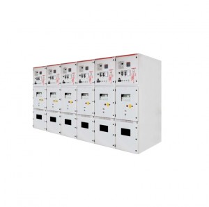
| RSF-12 series SF6 gas insulated ring network switchgear has the advantages of compact structure,full closure,full insulation,long service life,maintenance free,small space occupation,safety and reliability,and is not affected by the working environment.It is widely used in industrial and civil cable ring networks and power supply terminals.It is especially suitable for small secondary distribution stations,switching stations,industrial and mining enterprises,airports,railways,residential areas,high-rise buildings,highways, subways,tunnels and other fields. |
|||||||
| Operating environment | |||||||
| Name | Parameter | Name | Parameter | ||||
| RSF-12 series SF6 gas insulated ring network switchgear |
Generally operate/service under normal indoor conditions, complying with IEC 60694 |
Altitude | ≤1500 m(under standard inflation pressure) |
||||
| Ambient temperature | The maximum temperature is+40 ℃; Maximum temperature (24h average)+35℃; The minimum temperature is-40 ℃; |
SF6 gas pressure | Low than20℃,1.4bar (absolute pressure) |
||||
| Humidity | Maximum average relative humidity (24 hours measure=95%; monthly measure ≤90%) |
Annual leakagerate | 0.25 %/year | ||||
| Arcing test | With arc extinguisher 20kA 1s No arc extinguisher 16kA 1s |
Immersion test | 0.3bar pressure underwater 24kV 24h |
||||
| Cable bushing standard | DIN47636T and T2/EDF HN 525-61 | Protection degree |
SF6 air chamber IP67 Fuse cartridge IP67 Switch cabinet sell IP3X |
||||
- Online