


33kv metal-clad digital switchgear
● The Busbar features thermal shrinkage material, insulation with epoxy coating to ensure high insulation performance;
● The maintenance-free withdrawal vacuum circuit breaker (VCB) saves much maintenance for its supporting operating mechanisms;
● Additional lock device between circuit breaker compartment door and circuit breaker;
● A fast closing earthing switch is used for earthing and can close the short-circuit current;
● All operations can be made with the switchgear door closed;
● Reliable locking device efficiently prevents maloperation;
● Changeable VCB truck, easy for circuit breaker replacement;
● Pressure release device with air exhausting;
● Multiple cables connected in parallel;
● Convenient to monitor the circuit breaker ON/OFF and truck positions, mechanism energy storage status, earthing switch ON/OFF position and cable connections;
● The component installation board of low-voltage compartment features rear-arranged cables and removable rotation device, and the secondary cables are laid in the capacious cable Trunking for neat appearance and easy inspection.
Normal service condition
● Ambient temperature:
- Maximum: +40°C
- Minimum: -15°C
- Average of temperature measurements within 24 hrs <+35°C
Ambient humidity condition
● Relative humidity:
- Average of relative humidity measurements within 24 hrs <95%
- Monthly average of relative humidity <90%
● Vapor pressure:
- Average of vapor pressure measurements within 24 hrs <2.2 kPa
- Monthly average vapor pressure <1.8 kPa
- Max altitude of switchgear installation site: 1,000m
- The switchgear should be installed at a place free of fire, explosion hazards, serious filth, chemical corrosive gas
And violent vibration.
Special service condition
The special service conditions beyond the normal service conditions, if any, should be negotiated to enter into an agreement. To prevent condensation, the switchgear is equipped with a plate-type heater. When the switchgear is set up for a commission, it should be put into immediate use. Even when it is in normal service, attention should also be paid for the operation.
The heat dissipation problem of the switchgear may be addressed by providing additional ventilation device.
Standards and Specifications
1EC62271-100
High-voltage alternating-current circuit breakers
1EC62271-102
High-voltage alternating-current disconnectors and earthing switches
1EC62271-200
High-voltage alternating-current metal-enclosed switchgears and controllers for rated voltages above 1kV and up to and including 52kV
IEC60694
Common specifications for high-voltage switchgears and controller standards
lEC60071-2
Insulation co-ordination-Part 2: Application guide
IEC60265-1
High voltage switches-Part 1: Switches for rated voltage above 1kV and less than 52kV
1EC60470
High voltage alternating-current contractors and contractor-based motor-starter
General
ZS33 switchgear consists of two parts: the fixed enclosure and the removable part ("Circuit breaker truck" for short). Based on the functions of the electrical equipment inside the cabinet, the switchgear is divided into four different functional compartments. The enclosure and the partitions that separate the functional units are made of Al-Zn-coated steel sheets, which are bent and riveted together.
The removable parts may include a vacuum circuit breaker (VCB), SF6 circuit breaker, potential transformer, lightning arrester, insulator, fuse truck, etc. Inside the switchgear, a voltage presence indication unit (to be chosen by the user) may be installed to check the working status of the primary circuit. This unit consists of two parts: "the high-potential sensor installed on the side of the feed line and the indicator installed on the low-voltage compartment door.
The protection grade of the switchgear enclosure is IP4X, while it is IP2X when the circuit breaker compartment door is opened. Taking into consideration the impact of the internal failure arc on the structure of ZS33 switchgear, we conducted a strict arc ignition test to effectively ensure the safety of operating personnel and the equipment.
Enclosure, Partitions, and Pressure Release Device
The Al-Zn-coated steel sheets are machined with a CNC tool, bonded, and riveted to form the enclosure and partitions of the switchgear. So, the assembled switchgear has consistent dimensions and high mechanical strength is ensured.The door of switchgear is powder-coated and then baked, and thus it is resistant to impulse and corrosion and neat in appearance.
The pressure release device is provided on top of the circuit breaker compartment, busbar compartment, and cable compartment. In the event of an internal failure arc accompanied by an electric arc, the air pressure inside the switchgear will rise, and the pressure release metal board on the top will automatically open to release pressure and discharge air. The cabinet door is provided with a special seal ring to enclose the front part of the cabinet, so as to protect operating personnel and the switchgear.
Circuit breaker Compartment
In the circuit breaker compartment, there is a truck, and rails are provided for traveling off the truck. The truck is able to move between "service and test/Disconnect" positions. Installed on the rear wall of the truck compartment, the shutter is made of metal plates. The shutter automatically opens when the truck moves from the "Test/Disconnect* position to the "Service" position, while it automatically closes when the truck moves in the opposite direction, thus preventing operating personnel from touching any electrified bodies.
The truck can be operated while the door is closed. You may see the position of the truck inside the cabinet through the viewing window, the mechanical Position indicator of the circuit breaker, and the indicator of energy storage or energy release status.
The connection between the secondary cable of switchgear and the secondary cable of the truck is realized through the manual secondary plug. The dynamic contacts of the secondary plug are connected through a nylon corrugated pipe, while the secondary socket is located on the right side beneath the circuit breaker compartment. Only when the truck is in the "Test/Disconnect" position, can the secondary plug be plugged on or pulled off the socket. When the truck is in the "Service" position, the secondary plug is locked and cannot be released, due to the mechanical interlock. The circuit breaker truck can only be manually opened before the secondary plug is connected up, but it cannot be manually closed because the closing locking electromagnet of circuit breaker truck is not energized.
Truck
Cold-rolling steel sheets are bent, soldered, and assembled to form the truck frame. According to its purposes, the truck is divided into different categories: circuit breaker truck, potential transformer truck, isolation truck, etc. However, the height and depth of each track are the same, so they are interchangeable. The circuit breaker truck has "Service" and "Test/Disconnect" positions in the cabinet. A lock unit is provided with each position to ensure that the specific operations can be carried out only when the truck is in the specific position. The interlock condition has to be met before the truck is moved, so as to make ‘sure that the circuit breaker is opened before the truck is moved.
When the circuit breaker truck is pushed into the switchgear, it is in the "Test/Disconnect" position at first, and then it can be pushed into the "Service" position by rolling the handle.
The circuit breaker truck is built with an arc interrupter and its operating mechanism. The circuit breaker has independent three-phase poles on which the upper and lower contact arms of the petal-like contacts are installed. The secondary cable of the operating mechanism is laid out through a special secondary connector.
The position of the truck inside the cabinet is not only indicated by the position indicator on the low voltage compartment panel but also sighted through the viewing window on the door. The operating mechanism and closing/opening indicator of the circuit breaker are located on the truck panel.
Contacts System
For the ZS33 switchgear, the petal-like contacts are employed as the electric conduction units between the fixed contacts of the primary circuit and the dynamic contacts of the truck. With reasonable construction design and simple machining and manufacturing, the contacts system features easy maintenance, low contact resistance, excellent capability of withstanding short-time withstand current and peak withstand current, and other good electrical performances. By rolling in or out of the truck, the contact system contacts or disconnects easily, which makes truck operations very convenient.
Busbar compartment
The main Busbar extends through the neighboring cabinets and is supported by the branch bus bars and vertical partitions and bushings. Both main and branch bus bars are coated with heat shrinkage bushings or painting to provide reliable composite insulation effects. The bushings and partitions are to isolate the neighboring switchgears.
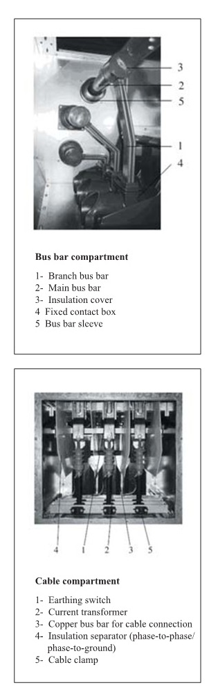
Cable compartment
The cable compartment can be equipped with current transformer and earthing switch (w/ manual, operating mechanism), and be connected with several parallel cables. It's very convenient for cable installation due to the large space inside the cable compartment.
Low-voltage compartment
The low-voltage compartment and its door can be equipped with various secondary devices according to different requirements. There is reserved metallic shield trench for secondary control cables and sufficient space for cable incoming and outgoing. The reserved trench for incoming and outgoing control cables of the switchgear to enter the low-voltage compartment is on the left; while the trench for control cables of the cabinet is on the right of the switchgear.
Interlock mechanism preventing mis-operation
The ZS33 switchgear is provided with a series of lock devices to prevent any dangerous conditions and maloperation that may lead to serious results at the root, so as to effectively ensure the safety of operating personnel and the equipment.
The lock functions are as follows:
● The truck can move from the "Test / Disconnected" position to the "Service" position only when the circuit breaker and earthing switch are in the ‘open position; vice versa (mechanical interlock).
● The circuit breaker can be closed only when the circuit breaker truck entirely reaches the"Test" or "Service" position (mechanical interlock)
● The circuit breaker cannot be closed, but only manually opened, when the control power breaks while the circuit breaker truck is in the “Test"or "Service" position (electrical interlock).
● The earthing switch can be closed only when the circuit breaker truck is in the "Test / Disconnected" position or is moved off the position (mechanical interlock).
● The truck can not be moved from the “Test / Disconnected" position to the "Service" position during the closing of an earthing switch (mechanical interlock).
● When the truck is in the "Service" position, the control cable plug of circuit breaker is locked and cannot be plugged off.
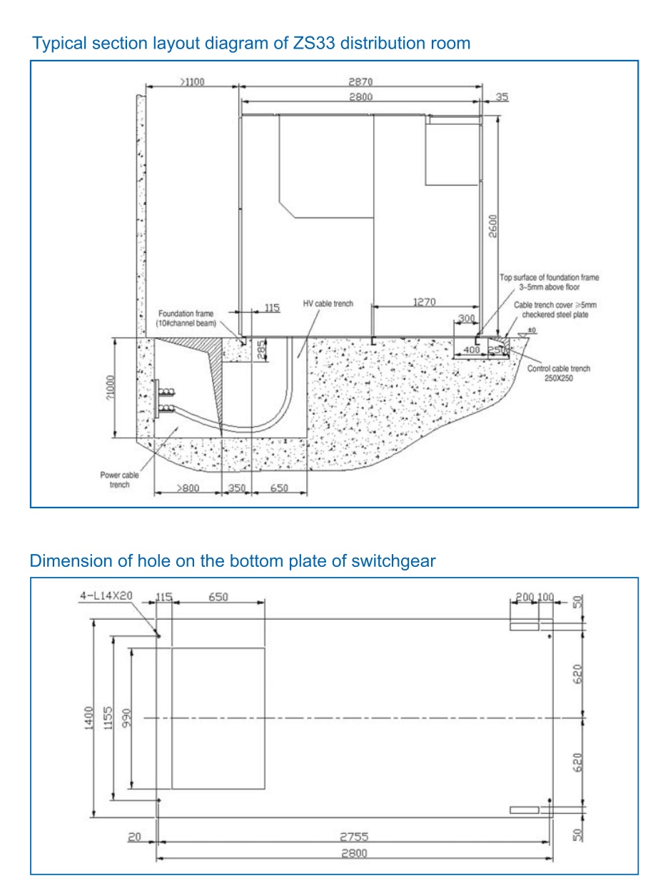
External dimension and weight of switchgear
| Height: 2600mm | Width: 1400mm | Depth: 2800mm | Weight: 950Kg-1950Kg |
Switchgear foundation embedment
The construction of switchgear foundation should comply with relevant regulations of electrical project construction and acceptance technical specifications.
‘The switchgear must be installed on the foundation frame which is fabricated according to the typical drawing provided by ‘Seven Stars and pre-embedded in the floor of distribution room,
To facilitate the installation, during the embodiment of foundation, relevant civil engineering regulations, in particular the
Linearity and levelness requirements of foundation in this Manual, should be complied with.
‘The number of foundation frames should be determined according to the number of switchgear. The foundation frame in general is embedded by constructors on site. If possible, it should be adjusted and checked under the supervision of Seven Stars technical staff.
● To meet the required surface levelness of foundation, the welding parts of the foundation frame should be welded on the planned points according to the stated procedure.
● The foundation frame should be placed accurately on the stipulated site of the concrete floor, according to the installation and arrangement drawing of distribution room.
● Use a level meter to carefully adjust the surface levelness of the entire foundation frame and guarantee the proper height. The top surface of the foundation frame should be 3~5mm higher than the finished floor of distribution room to facilitate the installation and adjustment of switchgear. In case of supplementary layer on the floor, distracting room, the thickness of the said supplementary layer should be considered otherwise. The allowable tolerance of foundation embedment should comply with DIN43644 (version A).
Allowable tolerance of levelness: ± 1mm/m2
Allowable tolerance of linearity: ± 1mm/m, but the total deviation along the total length of the frame should be less than 2mm.
● The foundation frame should be earthed properly, which must use 30 x 4mm galvanized steel strip for earthing.
In case of several switches gears in a long row, the foundation frame should be earthed on two ends.
● When the construction of the supplementary floor layer of distribution room is finished, special attention should be paid to the backfill at the bottom of foundation frame. Do not leave any gap.
● The foundation frame should be protected from any hazardous impact and pressure, in particular during the installation.
● If it fails to meet the above mentioned conditions, the installation of switchgear, movement of trucks and open of the truck compartment door and cable compartment door can be affected.
Switchgear installation
The ZS33 metal-clad & metal-enclosed switchgear should be installed in a dry, clean and well-ventilated distribution room.
The foundation frame and floor in the distribution room should be completed and pass the acceptance examination, and the decoration of doors and windows, lighting and ventilation equipment should be generally completed, before installation of switchgear.
Ordering instruction
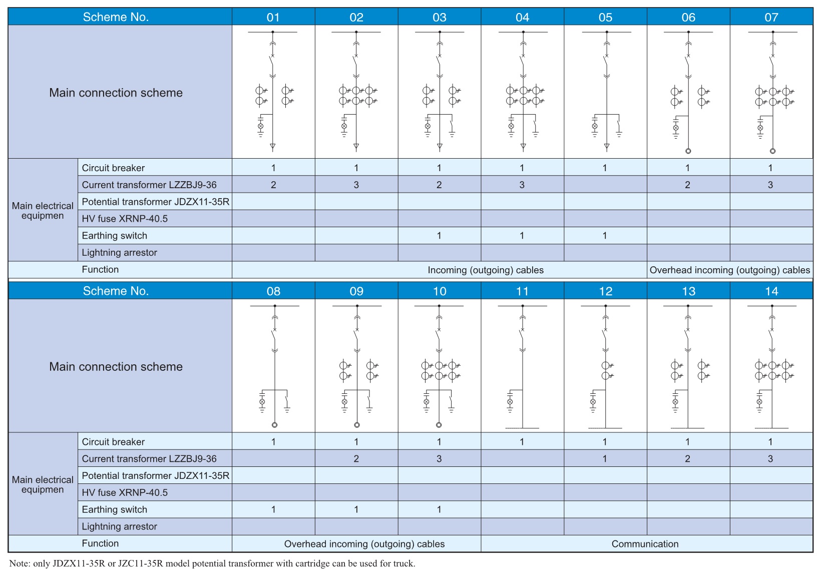
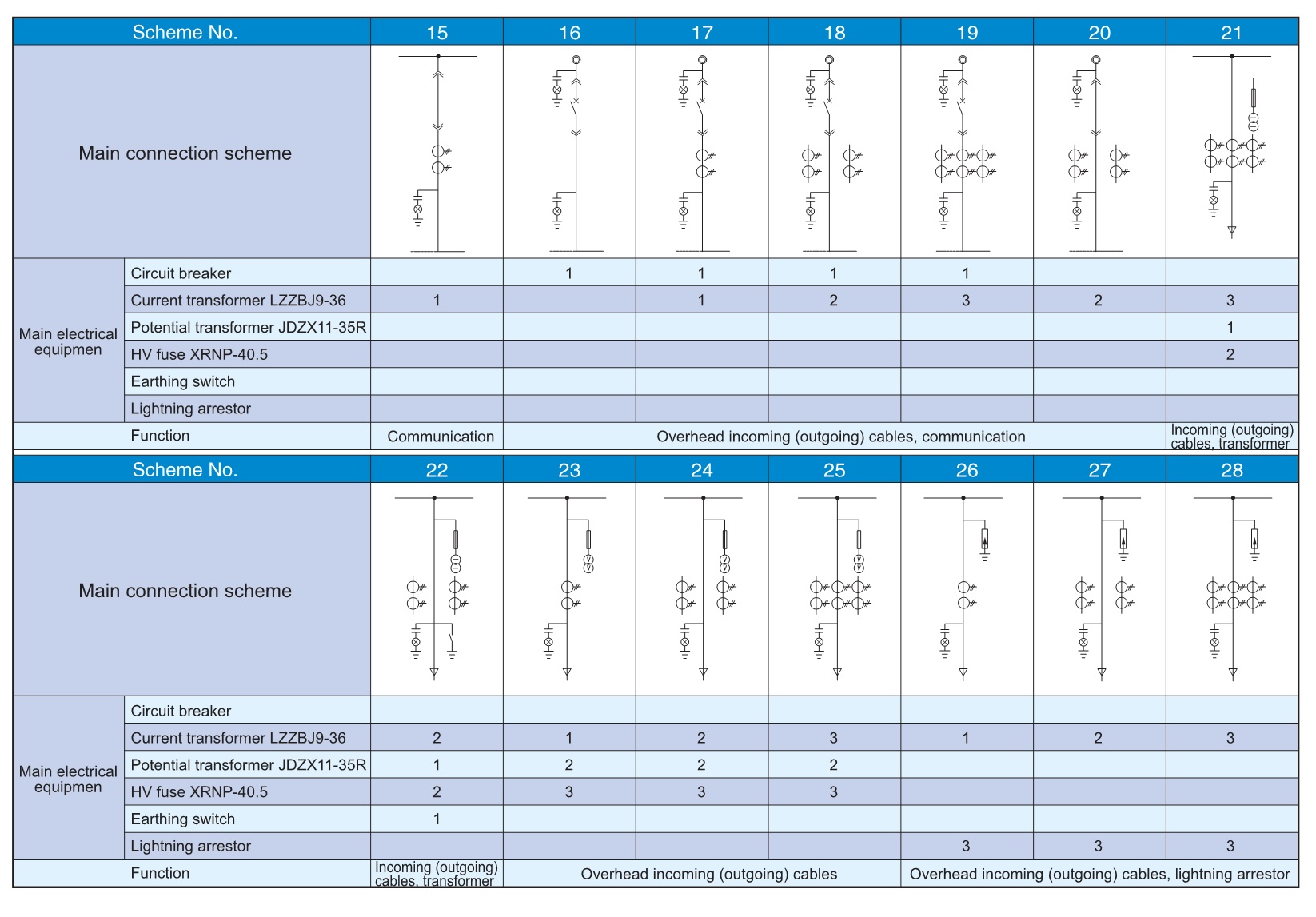
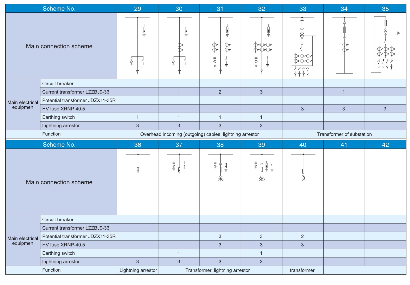
(1) No. & function of main connection scheme drawing, single line system diagram, rated voltage, rated current, rated short-circuit breaking current, layout plan of distribution room and arrangement of switchgear, etc.
(2) If incoming and outgoing power cables are used, the model and quantity of power cable should be noted in details.
(3) Requirements of switchgear control, measurement and protection functions, and requirements of other lock and automatic devices.
(4.) Model, specification and quantity of main electrical components in the switchgear.
(5) If the switchgear will be used under special service conditions, such conditions should be described in details when ordering

| Key Technical Parameters of ZS33 Switchgear | ||||||||||
| No | ltems | Unit | Ratings | |||||||
| 1 | Rated voltage | kV | 36 | |||||||
| 2 | Rated insulation level |
Rated power-frequency withstand voltage |
Phase-to-phase,phase-to-ground | 70 | ||||||
| Between contacts | 80 | |||||||||
| Rated peak withstand voltage |
Phase-to-phase,phase-to-grounc | 170 | ||||||||
| Between contacts | 195 | |||||||||
| Auxiliary power frequency withstand voltage | 2 | |||||||||
| 3 | Rated frequency | Hz | 50/60 | |||||||
| 4 | Main busbar rated current | A | 630,1250,1600,2000,2500 | |||||||
| 5 | Branch busbar rated current | 630,1250,1600,2000,2500 | ||||||||
| 6 | Rated peak withstand current | kA | 63/65,80/82 | |||||||
| 7 | Rated short-circuit breaking current of VCB | 2,531.5 | ||||||||
| 8 | Rated short-time withstand current (effective value) | 2,531.5 | ||||||||
| 9 | Rated duration of short-circuit | S | 4 | |||||||
| 10 | Internal failure arc (ls) | kA | 25 | |||||||
| 11 | Auxiliary power supply voltage (recommended)a | V | 110,220(AC,DC) | |||||||
| 12 | Overall dimension | mm | 1200(1400)x 2800×2600 (WxDxH) | |||||||
| a)Other auxiliary power supplies may be used if necessary | ||||||||||
| Technical Parameters of Key Components(1)V-Sa 36 kV vacuum circuit breaker | ||||||||||
| No. | tems | Unit | Value | |||||||
| 1 | Rated voltage | KV | 36 | |||||||
| 2 | Rated insulation level |
Rated short time power frequency withstand voltage (1 min) | 70 | |||||||
| Rated lightring impulse withstand voltage (peak | 170 | |||||||||
| 3 | Rated freguency | Hz | 50/60 | |||||||
| 4 | Rated current | A | 6,301,250 | 6,301,250 | 630,1250,1600,2000
2500,3150 |
1 | ||||
| 5 | Rated short-circuit breaking current | kA | 20 | 25 | 31.5 | / | ||||
| 6 | Rated short time withstand current | 20 | 25 | 31.5 | / | |||||
| 7 | Rated peak withstand current | 50/52 | 63/65 | 80/82 | / | |||||
| 8 | Rated short-circuit making current (peak | 50/52 | 63/65 | 80/82 | / | |||||
| 9 | Rated out-phase short-circuit breaking current | 17.3 | 21.7 | 27.4 | / | |||||
| 10 | Rated single/back-to-back capacitor bank breaking current | A | 630/400 | |||||||
| 11 | Rated short-circuit current duration time | S | 4 | |||||||
| 12 | Rated short-circuit current breaking times | Times | 30 | |||||||
| 13 | Rated operation sequence | Autoreclosure:O-0.3s-CO-180s-CO | ||||||||
| Non-autoreclosure:O-180s-CO-180s-CO | ||||||||||
| 14 | Mechanical life | Times | 20000 | |||||||
| 15 | Circuit breaker level | E2,M2,C2 | ||||||||
| The current transformers are in accordance with IEC 60044-1:2003 standards Rated insulation level:40.5/95/185KV Rated frequency:50/60Hz |
|||||||||||
| Rated secondary current:5A,1A | |||||||||||
| We can supply high precision current transformers of class 0.2S or 0.5S for measuring. Partial discharge:≤20PC |
|||||||||||
| Rated Primary Current |
LZZBJ9-36-36/250W3b(h,I) | ||||||||||
| 0.2-15VA | 0.2-15VA 5P10-15VA |
0.2-15VA 5P20-30VA |
0.2-15VA 5P10-15VA 5P20-30VA |
||||||||
| th kA/S | ldyn kA | th kA/S | ldyn kA | Ith kA/S | ldyn kA | lth kA/S | ld yn kA | ||||
| 15 | 4.5/1 | 11.5 | 4.5/1 | 11.5 | |||||||
| 20 | 6/1 | 15 | 6/1 | 15 | |||||||
| 30-40 | 10/1 | 25 | 10/1 | 25 | |||||||
| 50-60 | 17/1 | 42.5 | 17/1 | 42.5 | 10/1 | 25 | 7/1 | 18 | |||
| 75 | 25/1 | 63 | 25/1 | 63 | 17/1 | 42.5 | 10/1 | 25 | |||
| 100 | 25/2 | 63 | 25/2 | 63 | 25/1 | 63 | 17/1 | 42.5 | |||
| 150 | 25/3 | 63 | 25/3 | 63 | 25/2 | 63 | 25/1 | 63 | |||
| 200-250 | 25/3 | 63 | 25/3 | 63 | 25/3 | 63 | 25/2 | 63 | |||
| 300 | 31.5/4 | 80 | 31.5/4 | 80 | 25/3 | 63 | 25/3 | 63 | |||
| 400 | 31.5/4 | 80 | 31.5/4 | 80 | 31.5/4 | 80 | 25/3 | 80 | |||
| 500-600 | 31.5/4 | 80 | 31.5/4 | 80 | 31.5/4 | 80 | 31.5/4 | 80 | |||
| 750-1250 | 31.5/4 | 80 | 31.5/4 | 80 | 31.5/4 | 80 | 31.5/4 | 80 | |||
| 1500-2000 | 31.5/4 | 80 | 31.5/4 | 80 | 31.5/4 | 80 | 31.5/4 | 80 | |||
| 2500 | 31.5/4 | 80 | 31.5/4 | 80 | 31.5/4 | 80 | 31.5/4 | 80 | |||
| 3000-3150 | 31.5/4 | 80 | 31.5/4 | 80 | 31.5/4 | 80 | 31.5/4 | 80 | |||
| Note:Any special requirements should be negotiated with us first. | |||||||||||
| (3)JN22-36/31.5 earthing switch | |||||||||||
| No | ltems | Unit | Parameters | ||||||||
| 1 | Rated voltage | kV | 36 | ||||||||
| 2 | Rated insulation level |
Power-frequency withstand voltage(effective value | 70 | ||||||||
| Lightening impulse withstand voltage (peak) | 170 | ||||||||||
| 3 | Rated short-time withstand current (4s | kA | 31.5 | ||||||||
| 4 | Rated peak withstand current (peak) | 80/82 | |||||||||
| 5 | Rated short-circuit making current (peak) | 80/82 | |||||||||
Products categories
- Online