


17.5kV Ring Main Unit
SEVEN STARS SS SERIES COMPACT-RING MAIN UNIT UP TO 17.5 KV
★Reliable solution for power distribution networkSF6 gas for insulation and for load break switching functions
★Vacuum technology for fault breaking (VCB)
★Self-power relay for high level of protections in all conditions
★Reliable breaker mechanism operation with low power trip coil
★High quality full welded tank IP 67 with leakage rate less than 0.1% per year
★High protection against pollution and humidity by enclosure lP54
★Maintenance free and expected life of the product more than 30 years
★Safe and easy operation with full interlocking system and padlock options
★Integrated cable test facility
★Full Automation /smart functions

TYPE TESTED IN LABORATORIES ACCORDING IEC:
★ Dielectric tests:
★Measurement of the resistance of circuits
★Temperature-rise tests
★Verification of the protection
★Short-time withstand current and peak withstand current
★Internal arc tests (tank and cable compartments) Accessibility type A (sides FLR)
★short-circuit making and breaking test duties
★Making and Breaking test duties for switches
★Mechanical Endurance
Seven Stars SS series- fully complies with IEC standards and can be customized with more features to be comply with any customer specifications
| IEC-62271-200 | metal-enclosed switchgear and controlgear |
| IEC-62271-1 | AC switchgear and controlgear |
| IEC-62271-103 | AC switches |
| IEC-62271-100 | Circuit Breaker Standards |
| IEC-62271-102 | AC disconnectors and earthing switches |
| IEC 62271-213 | Voltage detecting and indicating system |
Relay,Earth fault indicator,capacitive voltage indicator,RTU and all electrical equipment are full comply and type tested according their related IEC standards
Seven Stars SS series- switchgear operates under normal indoor conditions:
★Maximum temperature: +75°C
★Minimum temperature: -40°C
★24-hour average maximum temperature: +35°C
★Humidity: Maximum average relative humidity (2 4-hour measurement) 95%
Maximum average relative humidity(1 month measurement) 90%
★In the case of installation without reducing the gas pressure: the maximum altitude is 1500 m
Seven Stars SS series- switchgear applications in outdoor operation:
★Altitude:≤4000m
★Ambient temperature: maximum temperature: +50 °C; The average temperature within 24h does not exceed +35°C
★Ambient humidity: 24h relative humidity average does not exceed 95%; The average monthly relative humidity doesn't exceed 90%
★Installation environment: the surrounding air is free of explosive and corrosive gases, and there is no violent vibration in the installation site impact, pollution level does not exceed THE lll. level in GB/T5582;
★Ground acceleration caused by earthquakes: below the horizontal direction. 3g, Vertically below. 15g
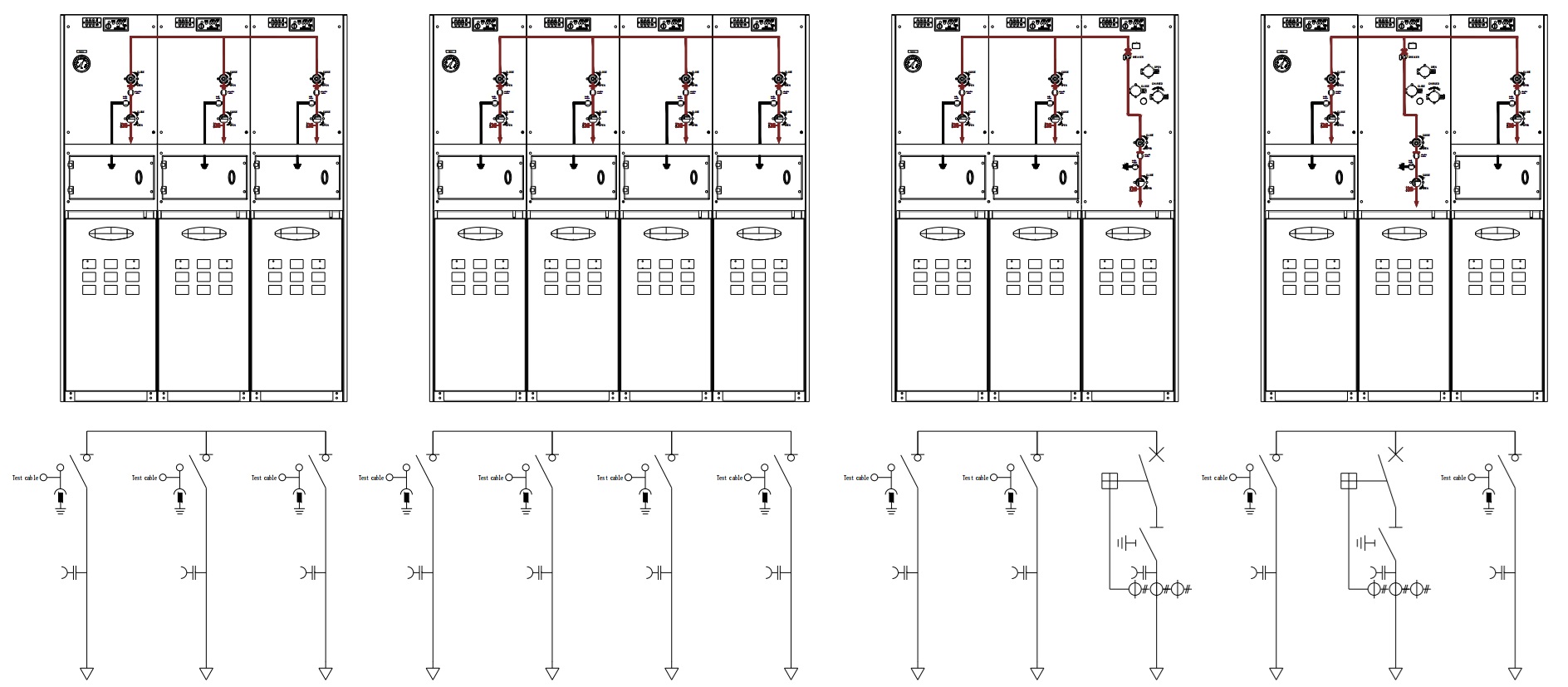
Seven Stars SS series- Ring design has a compact design up to 4 function units which can be arranged as in one compact tank without any extensions connection.
it has Load break switches and vacuum circuit breaker/s are full insulated by SF6 gas inside full welded stainless steel tank which is integrated with an embedded to enclosure lP54
The design allows for maximum space for easy power cable installation (750 mm from bushings to cable clamp) with width of cable compartment 400 mm
And at the same time keeping convenient height of operation mechanism and control compartment


| name | W | D | H |
| 3 ways-conventional | 1450 | 970 | 1600 |
| 4 ways-conventional | 1850 | 970 | 1600 |
| 3 ways-Automated (Smart) | 1450 | 970 | 1850 |
| 4 ways-Automated (Smart) | 1850 | 970 | 1850 |
★LTL : 3ways
★LLTL : 4ways
★LTTL : 4ways
★LLL : 3ways (switching RMU)
★LLLL : 4ways (switching RMU)
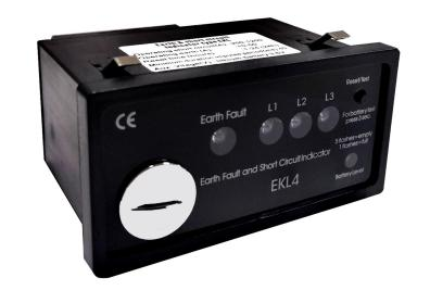
Fault Indicator
Fault indicators are widely used in various ring main unit, high-voltage switchgear and cable branch box of power system, which can accurately and reliably detect the fault section and fault type of the power grid. The use of cable short-circuit ground fault indicator is an efficient way to find cable faults, is an effective way to improve the operation level of the distribution network and the efficiency of accident handling. Low power consumption design, high-capacity lithium battery or external power supply, long battery life; external structure using card-type design, the whole machine is simple and convenient loading and unloading.
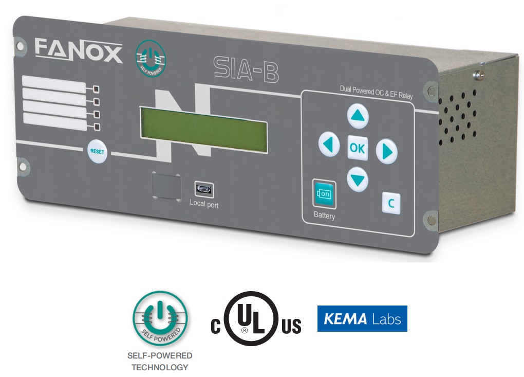
Microcomputer Protection Device
Self-powered microcomputer protection device has the advantages of high integration, complete protection configuration, strong anti-interference ability, low power consumption, resistance to harsh environments, etc. It is especially suitable for direct decentralized installation in the switchgear cabinet to realize the measurement, monitoring, control, protection, communication and other functions of the circuit breaker unit. Self-powered microcomputer protection and active microcomputer can be selected according to the actual needs, and our company will provide multi-brand options.
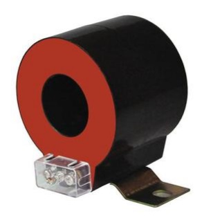
Current Transformer
Current transformer based on the principle of electromagnetic induction will be the primary side of the large current into the secondary side of the small current for power measurement, relay protection, automatic control and other devices to provide signals for power equipment, play a role in the protection and monitoring of primary equipment, the reliability of its work on the safe operation of the entire power system is of great significance.
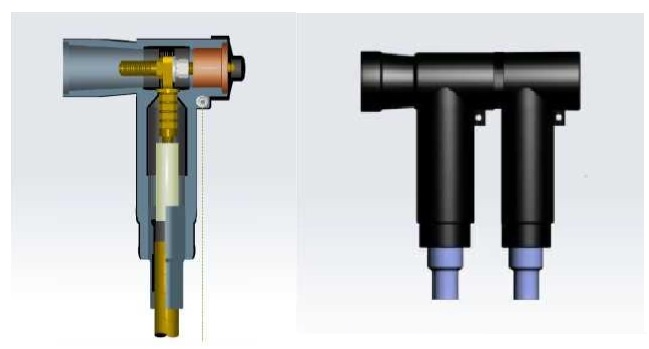
Cable Accessories

| Item | Unit | Load switch unit |
Circuit breaker unit |
| Rated Voltage | kV | 17.5 | 17.5 |
| Rated frequency | Hz | 60 | 60 |
| Rated current | A | 400 | 400 |
| Power frequency withstand voltage (phase-to-phase and relatively) | / | 38 | 38 |
| Power frequency withstand voltage(between fractures) | / | 45 | 45 |
| Power frequency withstand voltage(control and auxiliary loops | / | 2 | 2 |
| Lightning shock withstand voltage (phase-to-phase and relatively) | / | 95/110 | 95/110 |
| Rated for short-term withstand current | kA | 21/1s | 21/1s |
| Rated peak withstand current | kA | 54.6 | 54.6 |
| Rated short-circuit closing current | kA | 54.6 | 54.6 |
| Rated short-circuit breaking current | kA | / | 21 |
| Rated transfer current | A | / | / |
| Rated active load breaking current | A | 400 | / |
| Item Rated closed-loop breaking current | A | 400 | / |
| Mechanical life:load switch/circuit breaker | 次 | 5000 | 10000 |
| Mechanical life:isolation/grounding switch | 次 | 2000 | 1000 |
| Inflation pressure:Rated inflation pressure | Mpa | 0.04 | 0.04 |
| (G/C at 20℃) | % | ≤0.01 | ≤0.01 |
| Internal Arc Classification((indoor & outdoor) | 21kA/1s | ||
Products categories
- Online