


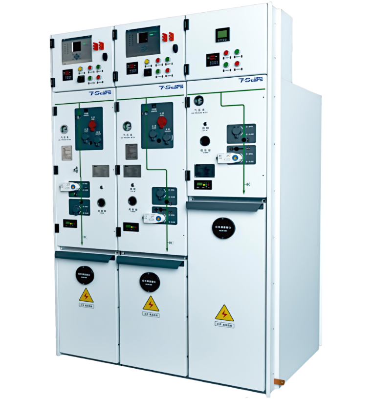
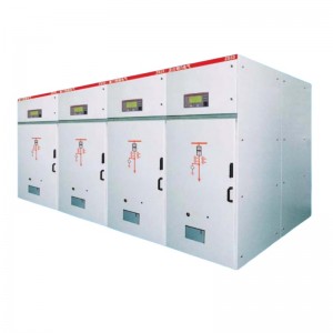
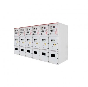
SSF-40.5kV series SF6 Gas Insulated Switchgear
★Altitude: Up to 4,000 meters (13,123 feet)
When the equipment is operating at an altitude of over 1000m, please specify it specifcally so that the charge pressure andchamber strength can be adjusted during manufacturing.
★Humidity: Average 24-hour relative humidity no greater than 95%
★Temperature: Maximum of +50°C
Minimum of-40°C
★The average temperature within 24 hours shall not exceed 35°C
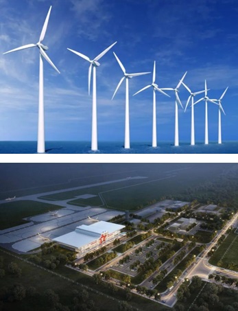
★Plateaus: Adapted to the unique environmental conditions of high-altitude regions.
★ Coastal Areas: Capable of withstanding the humid and corrosive conditions found near coastlines.
★High Cold: Robust enough to operate in regions with extreme cold temperatures.
★ High Pollution: Resistant to the harsh environments associated with industrial and urban settings.
★ Earthguake-Prone Regions: Earthquake resistant design ensures structural integrity up to an intensity of9 degrees
| NO | Name | Parameter |
| 1 | Rated frequency | 50Hz/60Hz |
| 2 | Rated voltage | 40.5kv |
| 3 | Rated current | 630A |
| 4 | Rated short-time withstand current | 20/4s-25kA/2s |
| 5 | Rated power frequency withstand voltage(/min) | 95/118ky |
| 6 | Rated lightning impulse withstand voltage | 185/215kV |
| 7 | Loss of service continuity category | LSC 2B |
| 8 | nternal arcing rating | IACA FL20kA/IS arranged against the wall lACA FLR 20kA/S arranged away from the wall |
| 9 | Switch/cubicle protection level | P67/IP4X |

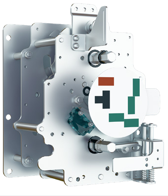
1 Main switch mechanism 2 Operation panel
3 lsolation mechanism 4 Cable compartment
5 Secondary control box 6 Busbar connecting bushing
7 Arc extinguishing device 8 Disconnector
9 Fully enclosed box 10 Pressure relief device inside the box
Cable compartment
• The cable compartment can only be opened if the feeder has been isolated or grounded.
• The bushing complies with DIN EN 50181 standard, M16 bolt connection, and the arrester can be connected behind the T- shaped cable adapter.
• The integrated CT is located on the bushing side, making it easy to install cables and not affected by external forces.
• The height from the bushing installation point to the ground is greater than 680mm .
| No | Standard | Standard name |
| 1 | GB/T 3906-2020 | 3.6kV~40.5kV AC metal-enclosed switchgear and control equipment |
| 2 | GB/T 11022-2011 | Common technical requirements for high-voltage switchgear and control equipment standards |
| 3 | GB/T 3804-2017 | 3.6kV~40.5kV high voltage AC load switch |
| 4 | GB1984-2014 | High voltage AC circuit breaker |
| 5 | GB1985-2014 | High voltage AC disconnector and earthing switch |
| 6 | GB 3309-1989 | Mechanical test of high voltage switchgear at normal temperature |
| 7 | GB/T13540-2009 | Anti-magnetic requirements for high-voltage switchgear and control equipment |
| 8 | GE T 13384-2008 | General technical conditions for packaging of mechanical and electrical products |
| 9 | T13385-2008 | Packaging pattern requirements |
| 10 | GB/T 191-2008 | Packaging,storage and transportation graphic signs |
| 11 | GB/T 311.1-2012 | Insulation coordination part 1 Definitions,principles and rules |
1 Main switch mechanism 2 Operation panel
3 Isolation mechanism 4 Cable compartment
5 Secondary control box 6 Busbar connecting bushing
7 Arc extinguishing device 8 Disconnector
9 Fully enclosed box 10 Pressure relief device inside the box
Cable compartment
• The cable compartment can only be opened if the feeder has been isolated or grounded.
• The bushing complies with DIN EN 50181 standard, M16 bolt connection, and the arrester can be connected behind the T- shaped cable adapter.
• The integrated CT is located on the bushing side, making it easy to install cables and not affected by external forces.
• The height from the bushing installation point to the ground is greater than 680mm


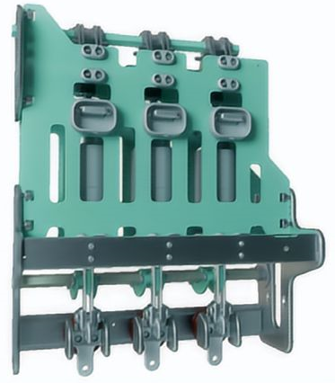
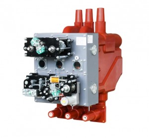
Load switch mechanism
Single spring and double operating shaft design ensures precise and controlled movement, eliminating the risk of excessive overshooting during opening and closing. Its robust mechanical construction boasts a lifespan exceeding 10,000 times, while its pre-designed electrical components facilitate easy installation and maintenance.
Three-position load switch
The load switch's three-position design, with separate positions for closing, opening, and grounding, ensures maximum safety and reliability. Its rotating blade and integrated arc extinguishing coil effectively extinguish arcs, delivering exceptional insulation and breaking performance.


Isolation mechanism (Disconnector)
Single spring dual operating shaft design, built-in reliable closing, open-ing, and grounding limit interlocking devices to ensure that there is no obvious overshoot during closing and opening. The mechanical life of the product is more than 10,000 times , and the electrical components are pre-designed to ensure Installation and maintenance are available at any time.
Designed in strict accordance with IEC, GB and DL related standards
| The main standards followed are as follows | |
| IEC62271-1 | General specification for high-voltage switchgear and controlgear |
| IEC62271-103 | with rated voltages above 1KV,52kV and below |
| IEC62271-102 | High voltage AC isolating switch and earthing switch |
| EC62271-200 | Metal-encased AC switchgear and control equipment with rated voltages above 1kv and 52ky and below |
| EC62271-100 | High voltage AC circuit breaker |
| EC62271-105 | High-voltage AC load switch-fuse combination electrical appliances with rated voltages above 1kv and 52kv and below |
| GB3906 | 3.6kV~40.5kV AC metal-enclosed switchgear and control equipment |
| GB3804 | 3.6kV~40.5V high voltage AC load switch |
| GB16926 | High voltage AC load switch -fuse combination electrical appliance |
| GB1984 | High voltage AC circuit breaker |
| DL/T 593 | Common technical requirements for high-voltage switchgear and control equipment standards |
| DL/T 402 | Technical conditions for ordering high-voltage AC circuit breakers |
| DL/T 404 | 3.6kV~40.5kV AC metal-enclosed switchgear and control equipment |
| DL/T 486 | Technical conditions for ordering AC high voltage isolating switches and grounding switches |
Arc extinguishing device and disconnector
The closing and opening mechanism employs a cam design, ensuring precise overtravel and full-travel dimen-sions, along with enhanced production versatility. The insulated side panels are meticulously manufactured using SMC molding, guaranteeing accurate dimensions and exceptional insulation strength. The disconnector's three-position design, encompassing closing, opening, and grounding functions, emphasizes safety and reliability.
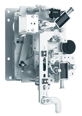
Circuit breaker mechanism
The precision transmission mechanism with reclosing function adopts V-shaped key connection. The shaft system support of the transmission system adopts a large number of rolling bearing design solutions. It has flexible rotation and high transmission efficiency, thus ensuring the product's mechanical life of more than 10,000 times.
The electrical components are designed to ensure Instal-
lation and maintenance are available at any time.
| Technical specifications | ||
| No | Name | Parameter |
| 1 | Rated voltage | 40.5kV |
| 2 | Rated power frequency withstand | 95KV/118kV |
| 3 | Rated lightning impulse withstand voltage | 185kV/215kV |
| 4 | Rated peak withstand current (Ip/Ipe) | to 63kA |
| 5 | Rated short-time withstand current (Ik/Ike) | 25kA |
| 6 | Rated duration of short circuit circuit (tk) | 2s |
| 7 | nternal arc withstand current,1s | 25kA |
| 8 | Rated frequency | 50/60Hz |
| 9 | Rated busbar current (IrBB) | 630A |
| 10 | Rated current(Ir) | 630A |
| 11 | Standard | GB3906 GB1984 GB3804 GB16926 |
| 12 | Protection leve | IP4X |
| 13 | Temperature range | -40℃ to +70℃ |
| 14 | Maximum relative humidity | 95% |
| Technical Parameters | ||
| Project | Unit | Parameter value |
| Conventional | ||
| Rated voltage | kV | 40.5 |
| Lightning impulse voltage | kV | 185/215 |
| Power frequency withstand voltage | kV-1min | 95/118 |
| Rated frequency | Hz | 50/60 |
| SF6 rated charge pressure | MPa | / |
| SF6 gas leakage rate | / | 0.05%/year |
| Intemal Arc Class (IAC) | kA/s | AFLR 20-1 |
| Air box protection level | / | IP67 |
| cubicle protection leve | / | IP4X |
| Protection level between compartments | / | IP2X |
| Partially placed in the whole cubicle | PC | ≤20 (1.1 Ur) |
| Load switch unit |
||
| Rated current | A | 630 |
| Rated short-aircuit dlosing current | kA | 50(63*) |
| Rated short-time withstand current | kA/s | 20-4 |
| Load switch mechanical life | / | M15000 times |
| Grounding switch mechanical life | / | M13000 times |
| Load switch electrical life | / | E3100 times |
| Circuit breaker unit |
||
| Rated current | A | 630 |
| Rated breaking current | kA | 20/25 |
| Rated short circuit making current | kA | 50/63 |
| Circuit breaker mechanical life | / | M1 10000 times |
| Disconnector mechanical life | / | M1 5000 times |
| Grounding switch mechanical life | / | M1 3000 times |
| Circuit breaker electrical life | / | 30 times,E2 level |
| Rated short-time withstand current | / | 20-4(25-2 |
| Rated operating sequence | / | 0-0.3s-C0-180s-C0 |
| Fuse combination electrical unit |
||
| Rated current | / | 125* |
| Rated short circuit breaking current | / | 31.5/80 (peak |
| Rated transfer curent | / | 1750 |
| Rated capacitive current breaking class | / | / |
| Note:*Depends on high voltage fuse. | ||


- Online